Design Tips
How to 3D print threads
Threads, typically seen on screws, bolts, nuts, and any other kind of fasteners are a helical structure that convert rotational motion into linear motion. The structure of the thread, as most commonly seen in screws has a slight ridge or groove that spirals around the body of the screw. Each screw or fastener is created for a variety of different purposes. For one, depending on the application of the screw, certain screws are created with specific leads (the linear distance a screw travels on one complete turn) to provide a mechanical advantage, but more importantly to keep your screw or fastener from slipping out when linear force is applied. Besides the lead, more considerations need to be made when designing a thread. For instance, when designing a thread, you first want to decide if you want your threads to be an external (male) or internal (female) thread. When creating either gender thread, be sure that the thread is properly designed to assemble with its off-gender counterpart.
Handedness
Describes wether the thread helix travels clockwise or counterclockwise
Form
Cross-sectional shape or geometry (square, triangle, trapezoidal, etc.) of the tread
Thread Angle
Angle characteristic of the thread geometry
Pitch
Distance from the crest of one screw to the next
Single, Double Triple, (etc.)
Amount of different ridges wrapped around a body
Coarse & Fine Thread
Further describes the pitch: course threads have a larger pitch or fewer threads per inch (TPI) while fine threads have a smaller pitch or larger threads per inch
Major Diameter
Diameter of the larger of the two diameters from a helical groove
Minor Diameter
Diameter of the smaller of the two diameters from a helical groove
Taper
Angle difference from one end of the screw to the other end (typically used for pipe fittings)
Designing Threads for Manufacturing
Typically, threads are built to a specific standard (metric or imperial), this makes designing threads fairly simple. Typically, when manufacturing a thread or screw, a threading mill is used to shave off material until the desired thread is formed, this process is subtractive in nature. A threading mill uses a tap and die to create the threaded feature.
However, with advancements in additive manufacturing technology, creating threads is now possible with 3D printing. Unfortunately, not all printing proesses can reliable produce threads, so it is important to choose the correct process when printing threads. Currently, the best process for printing theads is FDM due to its exceptionally high x/y dimensional stability. Other methods such as resin based or laser sintering based printing, have poor x/y dimensional when compared to FDM. With poor x/y resolution, it is near impossible to print threads because the x/y dimensions of threads are typically small. In addition to this, it is critical that the surface finish of the threads is as smooth as possible. With a poor surface finish, mating threads will be very difficult. The main drivers for surface finish are the part’s layer height and support material placement.
Support Material and Layer Height
Support Material
In most cases, your print will require some form of a support structure, as 3D printed parts are built layer by layer-building upon the previous layer and depending on how you orient your part can greatly affect how much support material is used and area where support material will be located, in toll affecting the surface finish when trying to remove the support material.
Depending on the printer and material, support material is need when an overhang is less than a certain angle. For our most popular material, Markforged Onyx, overhangs less than 45 degrees will require support material in order for the part to print properly. For overhangs greater than 45 degrees, support material is not necessary as the overhang is supported by enough of the previous layer, allowing the layer to be printed beyond the previous layer’s width. In short, the steeper your part’s overhang is, the less the need there is for support material to keep your part from sagging and becoming unprintable.
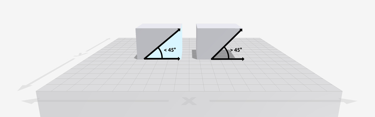
Overhang less than 45° requires support material, overhang above 45° does not require support material.
When printing threads, it’s important to orient your part to reduce the amount of support material within your threads. In some cases, you may be able to print a thread that doesn’t require any support material. This is possible because the overhangs are small enough that material can bridge a small distance without causing considerable sag in the part. But in most cases, you will need to orient your part to have the least possible amount of supports within its threads, this will help keep the thread’s surface finish smooth. Our quotation engine shows you exactly where support material will be placed.
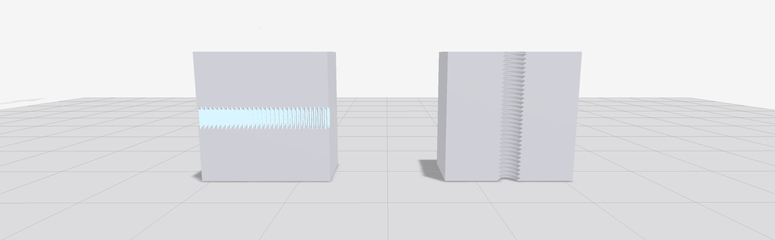
Left: Incorrect thread print orientation. Right: Correct thread print orientation.
Notice the support material placement when we orient the part incorrectly versus correctly. When oriented improperly, support material is located in between the threads resulting in a poor surface finish. When the part is oriented properly, no support material is used which will result in an excellent surface finish. The part’s printing orientation is important for both female and male threads.
Layer Height
A 3D printed part’s layer height or in other words the thickness of each layer can also be thought of as the part’s z-resolution. When we decrease the layer height of any 3D printing process, we are allowing more layers to be printed in a given part. This allows parts to have a better surface finish, but at the cost of an increase printing time. When printing a part, the designer will need to decide on what is more important to their project, good surface finish or short print time.
When printing any kind of thread (Metric, UNC, UFC, BSW, or Fine/Course), it is important to set the layer height to the lowest setting possible. At ProtoXYZ we use Markforged’s X7 3D printer for FDM processes. This allows us to provide parts with layer heights as low as 50 µm. Using a layer height above 50 µm will likely result in poor surface finish and render threads unusable.
Post Processing
Once your part is correctly oriented and set to the proper layer height, you are now ready to print your part! In some cases, your threaded part will be all set and ready to go without post processing, but most of the time some level of post-processing is necessary to remove support material from the threaded part. Using a pair of pliers or a pick, any support material that could be lodged in between the pitch of the threads is removed. And there you have it, a 3D printed part with threads!