Design Tips
STL files: What Are they and how to create them?
There are various CAD programs, software, and file formats that you can choose from when designing a model. Creating an STL file on some programs is as simple as a “Save As” and then the software does the rest. But have you ever wondered why STL files are popular in the world of Additive Manufacturing? Here is a brief overview on STL files and how to best design your next STL project for 3D printing with the greatest possible dimensional accuracy and surface finish.
The ".stl"
STL files or (Stereolithography, Standard Triangle Language, Standard Tessellation Language) is a file format created by Albert Consulting Group for 3D Systems in 1987. An STL file uses an approximation of the surface geometry of a 3D model at its most basic level, no colors or texture, just its basic surface geometry. When creating an STL file, the 3D object is described using triangulated surfaces to describe the figured body on the 3-point cartesian system. The STL file uses a data pool of dimensional coordinates and the normal vector to create the vertices of the surface triangle (which are perpendicular to the plane described by the points of a triangle).
Resolution, Tessellations, and More Triangles
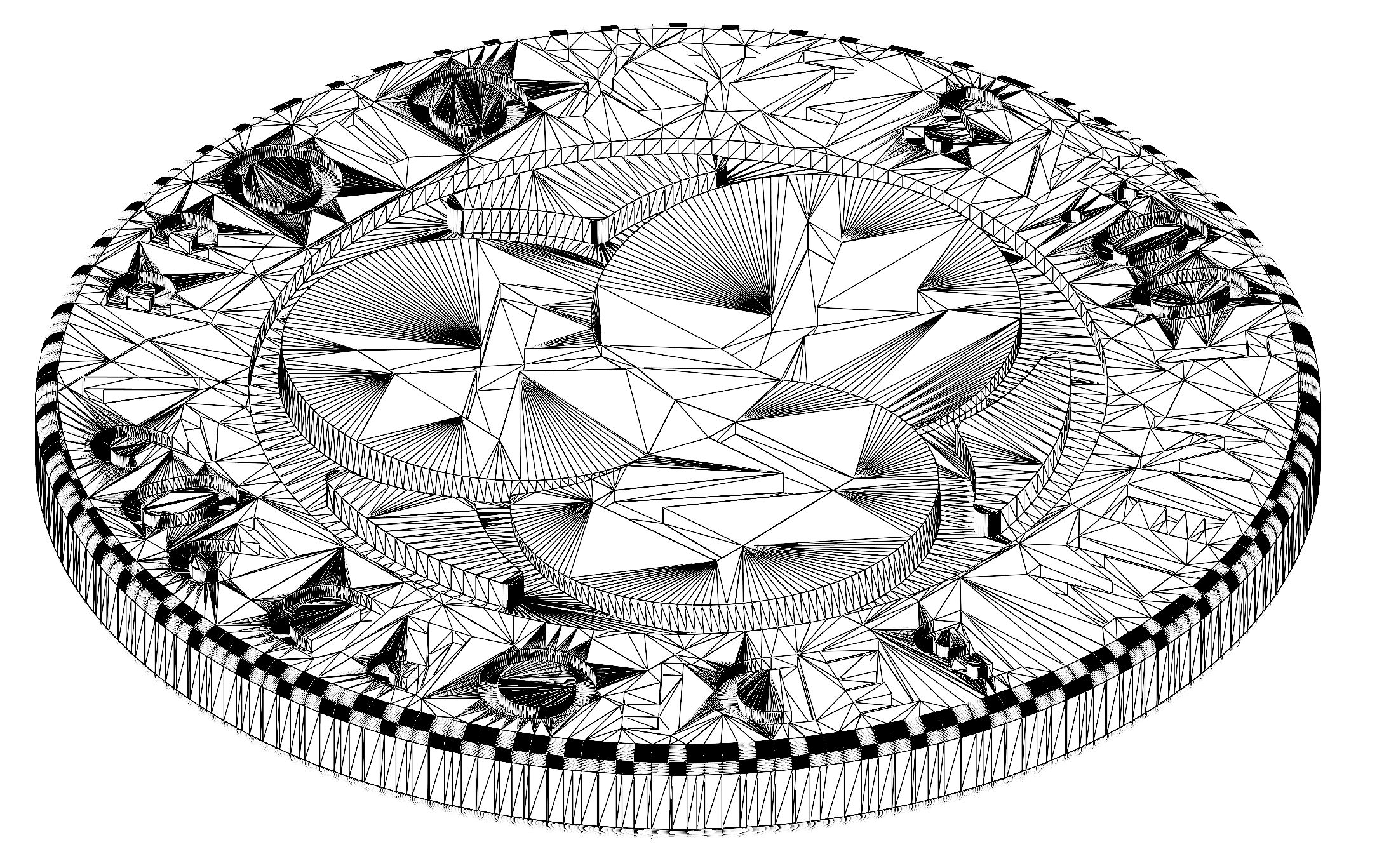
When we create multiple triangles on a surface, we begin to “tesselate” the solid model. Typically, when a model is tessellated, thousands of triangles are produced in the process to approximate the surface. When tessellating, if a rounded or curved surface has too few triangles on the surface, then the model would be printed flat or more commonly referred to as “faceted” like the sides of a gem. When printing your design, make sure that your part is tessellated enough to reduced faceted edges and faces on your desired model.
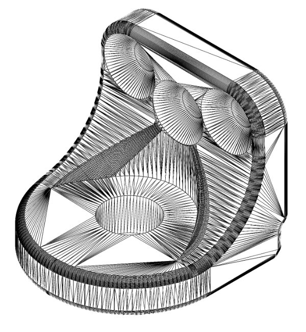
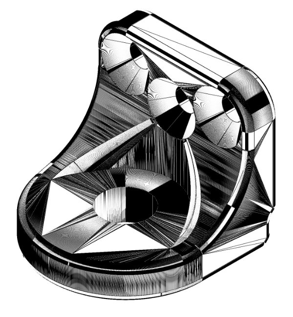
Note: More triangles do not always mean better file design as over tessellation generates files that are heavy to process. Flat surfaces do not need a significant amount of triangles to produce an accurate STL file.
Deviation Tolerances and Angle Tolerances
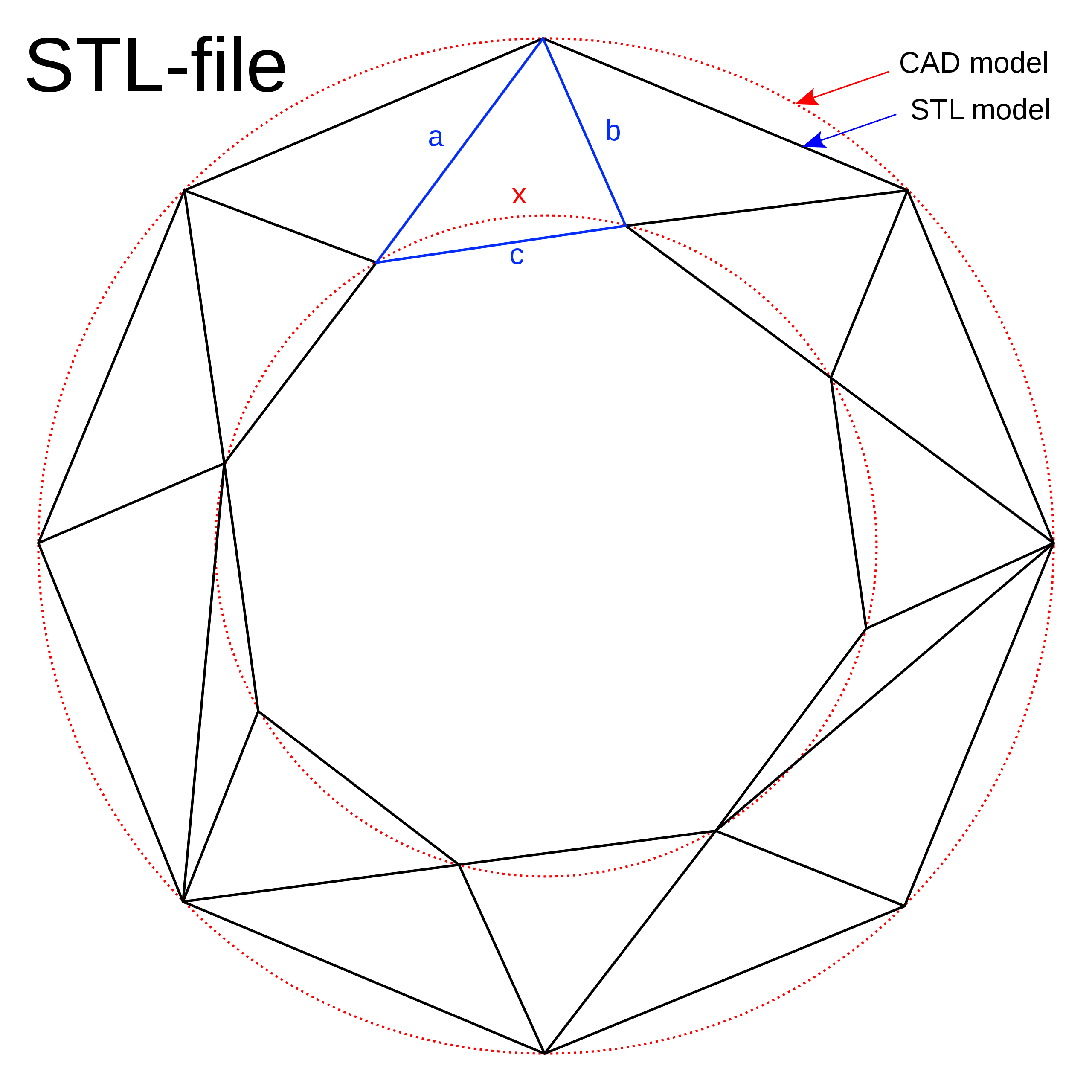
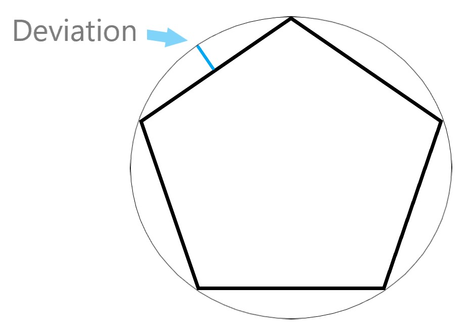
When you tesselate a surface, you may notice a slight difference between the STL file and your original design. This is described by the deviation tolerance, which determines how far away the tessellated surface can be from the native design. In practice, the lower the deviation the closer the resemblance.
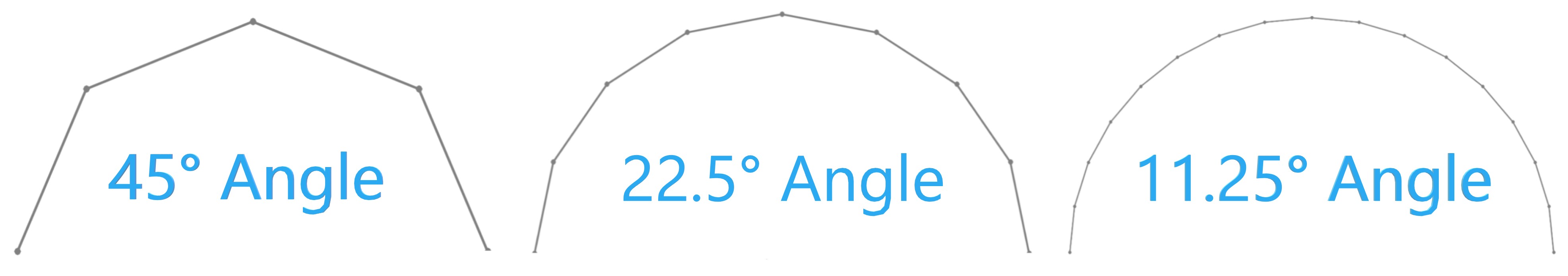
Angles tolerances in contrast are the direction a triangle face with regards to the triangles around it. In Lehman’s terms: the smaller the tolerance angles the smoother the surface. Having smaller Angle Tolerances will ultimately affect your file size, so keep that in mind when creating your next project. Deciding the Deviation and Angle for your STL file can have its challenges as every geometry has its best setting for it. We recommend using the setting that utilizes both tolerances at first- then adjust and change as you as your project fits. To view these settings- open your generated STL file and take a look. Viewing STL on your operating software can also be helpful to choose a desired Angle and Deviation tolerance that best matches your parts metric and file sizes.
Common Mesh Errors
Boundary Edges
Boundary edges are detected by our quotation engine's Printability Analysis if the model contains edges that are connected to only one face. When an edge is connected to only one face, the mesh is not solid and essentially contains a hole. If the Boundary edge is small, it will likely not result in a catastrophic error when printing. Nevertheless its always a good practice to repair your mesh before having it manufactured.
STL file with boundary edges
Non-Manifold Edges
Non-manifold edges occur when more than two faces share the same edge. Sometimes a surface can be inside of a solid model, resulting in non-manifold edges. More commonly though, two objects can share the same exterior edge, resulting in a non-manifold edge. This error rarely results in printing errors but should still be taken into consideration when creating STL files.
STL file with non-manifold edges shared by more than one bodies
STL file with non-manifold edges interior to the model
STL File Creation Walkthough
SolidWorks
File >Save As
Set Save As Type to STL
Options > Output As=Binary, Unit = Inches
Resolution > Custom
• Deviation Tolerance = Minimum (Slide bar to right)
• Angle Tolerance = 5 degrees
Click "OK"
Click "Save"
AutoCAD
Your design must be a three-dimensional solid object to output an STL file.
Make sure the model is in positive space
Set Facetres to 10
At the command prompt type STLOUT
Select Objects
Choose Y for Binary
Choose Filename
Rhino
File >Save As
Select File Type >STL
Enter a name for the STL file.
Save
Select Binary STL Files
ProE/Creo
File >Save a Copy
Set type to STL
Set chord height to 0. The field will be replaced by minimum acceptable value.
Set Angle Control to 1
Choose File Name
OK